3D printer bed leveling
Posted
#1
(In Topic #781)

Regular
PartierSP said
Yes. But since the first pass on a printer is always at a non zero height, the program is expecting to have that gap as your first pass, nothing more. And this makes sense compared to traditional CNC programming/machining practices in general (Z zero is usually top or bottom of the part, generally not somewhere in between).
So essentially your first pass wont have enough plastic resulting the expected pressure against the bed and/or each pass on the first layer will be spaced out too much not getting enough pressure against each other. Now the shim you're using is a very thin one so I don't expect you'll notice too much. Its just you're not at the 'theoretically perfect'. And if you use glue on your bed you may be easily making up for this extra gap and some. But one thing I've learned with automated equipment, if it works for you, then it works for you.
I have heard of people getting so called 'elephant's foot' error on their prints. This is where the first layer (or first few layers) bulge out at the bed. I'm not sure if this is a sign of the nozzle being set too low on the first pass, or a temperature issue, or what. But its something to look out for if you try new techniques.
Thanks for your input Mike. What you say makes a lot of sense.
I thought we'd better wander into the Lounge to continue our chat, since this is more about 3D Printing than Gambas programming.
I moved away from using copying paper to set/check the gap because it is compressible. Hence I'm using a 1960s set of steel feeler gauges, which were made before we introduced the metric system, over here in the UK. The 2, 3 & 4 thou gauges are very approx equal to 50, 75 & 100 micro-metres. From my comparative checks, it looks like a sheet of 70gsm paper is around 80um (0.08mm) thick.
Earlier this year, I did a few tests with my printer where I compared results with the the nozzle-to-bed gap set to 2, 3 & 4 thou. I was printing with a 0.4mm nozzle and a layer height of 0.2mm. My printer seemed to print OK with a 3 thou gap, but when set to 2thou, the first layer was smeared on the bed. My conclusion was that the nozzle was too close to the bed, although it was not touching it.
I rationalized this by thinking that the bead of molten PLA was being 'pulled' slightly at 90 degrees to the nozzle, maybe at a rate slightly faster or slower than the x/y movement of the bed. (sounds a bit crazy now I've written it down!). But of course, if the extruded PLA does curl very slightly (due to this small extra gap) and stick to the bed, subsequent layers will do exactly the same, and all layer heights will be roughly equal. In my earlier example, the final layer will still be printed approx 0.075mm below the nozzle.
However, the next time I have a spare evening, I'll run these checks again and also try the 'no-gap' configuration. Have you noticed any smearing? How do you compensate for the paper thickness when you dial in a Z value?
Re: using glue, hairspray, blue tape… to help stick prints to the bed… I've always thought that a crazy idea. I have a glass bed and just keep my fingers off of it. I clean the bed with isopropyl alcohol (IPA) from time to time, and that's all I seem to have to do for good adhesion.
Elephants foot generally seems to be caused by either lack of cooling or too high a bed temperature (the first few layers should be printed with the cooling fan off, then the rest with it on.

Posted
Regular
So far I've liked the feeler gauge much better then using paper. I haven't had any issues except if I mess around with the printer (possibly bumping the bed levelling knobs) and didn't re-level. I'm also waiting to see what will happen after running it for a year or two. I'm sure I'll start to develop some backlash in the Z, especially right near the bed where it moves (and hence wears) the most. If I do develop backlash, I may find I simply need to run my program telling it my shim's thickness is it's thickness + backlash distance to compensate.
I want to have a closer look at how my printer homes. I know it bounces on/off the limit switch at least twice. **edit see below** But if it does the final movement in the down direction, the backlash will show up in the first layer as its the first movement in the other direction. It would be much better if Z home is determined by moving Z up off of the limit switch. Then the backlash would be eliminated for printing as the head only moves upwards throughout the entire print.
But there are other ways to deal with backlash. I could use my program as normal, but if I could force a 'Z-Hop' prior to printing each layer in Cura, then my system should be spot on as the Z-Hop would replicate the movement my Levelling system does when finding Z-zero.
**Edit**
My printer just finished its print and am able to check the Z homing. Z will move down at a medium speed until it turns on the Z home limit switch. Then it moves up 1 or 2mm so Z home limit switch is off again. Finally it moves down slowly until the switch just barely turns on. Done. This means all your backlash will be taken up by your first layer as its the first move in the other direction. :? I guess what can they do when they only use a single switch for each axis.
Posted
Regular
Actually that doesn't sound as crazy as it may seem. 3D printers are a constant volume devices. Meaning the volume of plastic passing by the extruder is equal to the volume of plastic being ejected out of the nozzle. Their velocities however are different. But by changing the nozzle diameter, you can change the velocity of the plastic ejecting out of the tip. But this speed doesn't have to be perfectly set to the velocity of the X-Y travel as plastic is um, plastic. That's plastic as in deformable. But this velocity difference between the extrusion and X-Y will build up some stresses and the bead will pull like an elastic (I've had that occasionally just at the start of a print).stevedee said
Earlier this year, I did a few tests with my printer where I compared results with the the nozzle-to-bed gap set to 2, 3 & 4 thou. I was printing with a 0.4mm nozzle and a layer height of 0.2mm. My printer seemed to print OK with a 3 thou gap, but when set to 2thou, the first layer was smeared on the bed. My conclusion was that the nozzle was too close to the bed, although it was not touching it.
I rationalized this by thinking that the bead of molten PLA was being 'pulled' slightly at 90 degrees to the nozzle, maybe at a rate slightly faster or slower than the x/y movement of the bed. (sounds a bit crazy now I've written it down!). But of course, if the extruded PLA does curl very slightly (due to this small extra gap) and stick to the bed, subsequent layers will do exactly the same, and all layer heights will be roughly equal. In my earlier example, the final layer will still be printed approx 0.075mm below the nozzle.
If we know our extruder velocity, our PLA filament diameter, and our nozzle tip diameter, then we can calculate out our extrusion speed: Vn=(Ve*Df^2)/(Dn^2)
Where:<LIST>
- <LI>
- Vn = Velocity at the nozzle (mm/s)</LI>
<LI> - Ve = Velocity at the extruder (mm/s)</LI>
<LI> - Df = Diameter of filament (mm)</LI>
<LI> - Dn = Diameter of nozzle (mm)</LI>
So, if you're lagging behind on the extrusion, we'd probably want to reduce the size of the nozzle hole a bit. The question then is how's your nozzle? Is the hole wearing at all? My printer came with a spare so I expect they are highly wearing parts.
I did have some smearing at the start. Heck day one I put a gouge in the plastic build surface that came with my Ender 3.However, the next time I have a spare evening, I'll run these checks again and also try the 'no-gap' configuration. Have you noticed any smearing? How do you compensate for the paper thickness when you dial in a Z value?
 ops: Yep, kinda too close there. I've just bought my first 2 spools of Overture PLA and they both came with free build surfaces that appear similar to my Ender's original, just smaller (200mm x 200mm).
With you there 100%!Re: using glue, hairspray, blue tape… to help stick prints to the bed… I've always thought that a crazy idea. I have a glass bed and just keep my fingers off of it. I clean the bed with isopropyl alcohol (IPA) from time to time, and that's all I seem to have to do for good adhesion.

Ah so the print is basically running at the bottom. Yes then I could see that as being temperature issues then.Elephants foot generally seems to be caused by either lack of cooling or too high a bed temperature (the first few layers should be printed with the cooling fan off, then the rest with it on.
Posted
Regular
PartierSP said
…I'm sure I'll start to develop some backlash in the Z, especially right near the bed where it moves (and hence wears) the most. If I do develop backlash, I may find I simply need to run my program telling it my shim's thickness is it's thickness + backlash distance to compensate.
Its very important to carryout routine maintenance on 3D printers. This includes checking for free-play and making adjustments to minimise it; especially maintaining belt tension and replacing worn rollers.
Also remember that during printing, Z doesn't only keep going up, it sometimes goes down. (I may have to trawl through some g-code if you need some examples).
I want to have a closer look at how my printer homes…
Yes, it tries to creep up on the limit switch in an attempt to find the same position every time. Not only is this a compromise (e.g. the slower the better for accuracy, without testing the patience of the user) but the limit switch on my printer is just a simple micro switch which contains a spring…so spring temperature is also a factor in where the extruder comes to rest. I wonder what repeatability looks like; i.e. within umetres, tens of umetres?
Posted
Regular
PartierSP said
…3D printers are a constant volume devices. Meaning the volume of plastic passing by the extruder is equal to the volume of plastic being ejected out of the nozzle. Their velocities however are different. But by changing the nozzle diameter, you can change the velocity of the plastic ejecting out of the tip. But this speed doesn't have to be perfectly set to the velocity of the X-Y travel as plastic is um, plastic…
Yep, I certainly struggle to visualise Plastic Dynamics…I may have just invented that terminology!
I can't really visualise how you get an apparently uniform 0.2mm diameter bead/string of plastic out of a 0.4mm diameter orifice (nozzle).
I guess you haven't had the joy of replacing a nozzle yet. If you were worried about burning your fingers during bed-leveling, just wait til you have to step the nozzle temperature up to 260'C to replace it. Yes, brass nozzles wear out surprising quickly. See my post: Captain Bodgit: 3D Printing: time to replace the nozzle?…The question then is how's your nozzle? Is the hole wearing at all? My printer came with a spare so I expect they are highly wearing parts…
My [current] recommendation is to buy a dozen cheap nozzles.
Posted
Regular
Several years ago I started to build myself a 3D printer. It was roughly based off of a Mendle Max, but I was going to give it a more industrial build (aka, stainless steel tubing, CNC cut plates, etc). I got the design, frame, and electronics completed and started to work on the slides. But my work vs play lives got all out of wack and wasn't able to spend time at it any more. So needless to say, I studied a fair amount on their designs and theory of operation. Everything I learned about the electronics were found on the RepRap forums. I haven't been back there in a few years so not sure what they've been up to. If you want, I'll get photos of how far I got with that printer.stevedee said
Wow! At last an intelligent discussion on 3D printers…thanks for sticking with me! (…a lot of the chat on the Creality forum is very low level, maybe there is a better forum I should be following)
My biggest problem is besides the past month or so with this printer, I have only done a few prints at the library. Otherwise I've had no direct experience with a 3D printer. And this is where I really need to learn off of people like you who have been running them for a while. 8-)
Yep maintenance is SO important! I can never stress it enough to my brother at work. Its nice to just turn on a machine and run, but it needs to always have that once over first.Its very important to carryout routine maintenance on 3D printers. This includes checking for free-play and making adjustments to minimise it; especially maintaining belt tension and replacing worn rollers.
I'll have a closer look too. I haven't noticed much up/down other then the up commands between levels. I have noticed Cura tends to do supports first, then walls, and finally infill. Maybe it does a Hop between on of them. I know there are Z-Hop options that they normally keep hidden from settings bar on the side, but if you search the hidden sections for 'Hop' you'll see it under the Travel section. I played with this a bit when I was doing a few tall and skinny prints. The nozzle kept knocking the print off of the bed when it would rapid across the part (I've since found using a Brim and adding the occasional support helped that out a lot).Also remember that during printing, Z doesn't only keep going up, it sometimes goes down. (I may have to trawl through some g-code if you need some examples).
Maybe that's something I'll do over Christmas/New Years. We've got a large old school dial indicator that's in 0.0001" (~0.0025mm) graduations. For I'm sure my Ender has the same micro switches that yours has. Hmmm, I think I may have another upgrade for this printer. Maybe I'll fit one of the Opto-Endstops I made for my other printer to this one (This was the page I used to build my electronics from: Gen7 Board - its basically an Arduino Mega without the Arduino boatloader flashed onto it). It would be a good comparison. And even if it doesn't improve the performance, it would add an indicator LED so I could see when its tripped.Yes, it tries to creep up on the limit switch in an attempt to find the same position every time. Not only is this a compromise (e.g. the slower the better for accuracy, without testing the patience of the user) but the limit switch on my printer is just a simple micro switch which contains a spring…so spring temperature is also a factor in where the extruder comes to rest. I wonder what repeatability looks like; i.e. within umetres, tens of umetres?
Posted
Regular
Lol! And don't forget to throw some Thermo Dynamics into the mix too! Thermo Plastic Dynamicsstevedee said
PartierSP said
…3D printers are a constant volume devices. Meaning the volume of plastic passing by the extruder is equal to the volume of plastic being ejected out of the nozzle. Their velocities however are different. But by changing the nozzle diameter, you can change the velocity of the plastic ejecting out of the tip. But this speed doesn't have to be perfectly set to the velocity of the X-Y travel as plastic is um, plastic…
Yep, I certainly struggle to visualise Plastic Dynamics…I may have just invented that terminology!

Oi I think I just made my head hurt!

Just think of it as a pub just opening up in the evening. Everyone runs in each taking a seat at the bar. Um ok, I don't think that ever happened nicely in a pub before. So yeah. Good question.I can't really visualise how you get an apparently uniform 0.2mm diameter bead/string of plastic out of a 0.4mm diameter orifice (nozzle).

Actually its probably just due to the consistent pressure that builds up within the nozzle tip and the constant velocity. I've always been amazed by how nicely a robot can lay a bead of weld, or a lathe on power feed can cut a shaft. Try to do this by hand and you'll always spot the human's work vs machine's.
HOLLY MOLLY! That's some wear! :shock:I guess you haven't had the joy of replacing a nozzle yet. If you were worried about burning your fingers during bed-leveling, just wait til you have to step the nozzle temperature up to 260'C to replace it. Yes, brass nozzles wear out surprising quickly. See my post: Captain Bodgit: 3D Printing: time to replace the nozzle?
My [current] recommendation is to buy a dozen cheap nozzles.
I know it was bothering me everytime the nozzle would rapid across the printed part. Sounded like a file banging against the print. Here its the file banging against the nozzle. Maybe I should look into Z-Hop some more.
Posted
Regular
PartierSP said
Several years ago I started to build myself a 3D printer… If you want, I'll get photos of how far I got with that printer.
Yes, please post a couple of photos.
…And this is where I really need to learn off of people like you who have been running them for a while.
I'm no expert. I was hoping to learn quality stuff from people who knew what they were talking about, but so much stuff on the net is just Chinese Echos (i.e. stuff that gets repeated that has either become corrupted, or was never right in the first place). Just because you find 10 websites that say exactly the same thing, it doesn't make it right!
… I know there are Z-Hop options…
Yes, I have Z-Hop on, and that's a good example as to why you can't accept free-play in the Z axis.
Maybe that's something I'll do over Christmas/New Years. We've got a large old school dial indicator that's in 0.0001" (~0.0025mm) graduations. For I'm sure my Ender has the same micro switches that yours has….
(Click to enlarge)
Posted
Regular
PartierSP said
…Just think of it as a pub just opening up in the evening….
Hmmm! Beer!
…so I'm back from the pub and I think I've got it.
For a 0.2mm layer from a 0.4mm nozzle, the layer is simply a flat strip of plastic, 0.2mm high by 0.4mm wide. Its drawn out into that shape by the relative flow rate and linear X/Y speed of the extruder.
Still not sure why the starting point (where the plastic initially attaches itself to the bed) is not just an ugly blob shape!
Posted
Regular
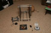
You asked about my printer I was making, I've attached a few pictures of it here. I need to look in my work shop to find the opto endstops I made. They weren't with the rest of the printer. But I'm sure they'll show up.
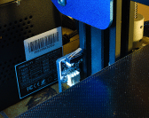
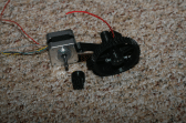
This is the overall shot of the printer and components. The printer was loosely based on the Mendel Max. Thus an A frame design with moving Y axis bed, duel stepper motor drive Z axis, and X axis gantry. In the bags at the lower right are the drive belts and pulleys. To the left is a programmer I made to flash Marlin (or which ever OS in there I want) onto the controller board. Left of that is the hot bed with the controller board that I made sitting on top. Extruder is to the left of that, and finally the bed support
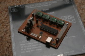
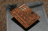
Top side of the controller.
(Click to enlarge)
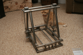
The main frame is shown here (along with the inspector).
Main Frame
(Click to enlarge)
Over all shot of the printer and components.
(Click to enlarge)
Posted
Regular
Extruder
(Click to enlarge)
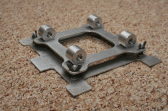
Here is a view of the bottom of the bed support. You can see the wing nuts and springs used to support the bed and allow for tramming. Its not completed yet. I was still working on making bushings or ordering linear bushings. I didn't make up my mind what I was going to do as original linear bearings were dang pricey. But looking on line I could probably pick something up for a decent price.
Bottom view of the bed support.
(Click to enlarge)
Here is a close up of the extruder. Its a simple 3D printed extruder using herringbone gears. Personally I liked the look of the gears and thought it would add a bit of steam punk look to it.
Bottom side of Controller
(Click to enlarge)
Posted
Regular
Posted
Regular
I do hope you find the time to complete this project, and maybe compare its performance with your Creality Ender.
But I know how difficult it is to find time for long term projects, with so may other demands on your time.
I have to confess that I have not used my printer since mid-October, and even then I was just demonstrating it to a mate that came over one evening. I haven't been able to find anything I wanted to print during the last couple of months.
PartierSP said
…It makes sense that Creative uses the same components for their entire line of printers.
I thought Creative made sound cards!
Those little micro-switches seem to do the job, its just that I would have thought the repeatability and hysteresis would have affected Z-zero, the very thing that needs to be spot-on. Also, I should imagine opto-source/sensor arrangements come with their own set of issues due to light-scatter, and maybe variations in sensitivity. Another consideration is how to ensure that if the motor drives through the detection point, the motor doesn't then get switched back on and damage something. At least with a micro-switch, once its operated, it stays operated. I also assume that they are wired in a relatively fail-safe manner, i.e. switch "open" stops the motor rather than "closed".
Your frame is a work of art (even the cat thinks so!). What is at the heart of your controller (...Arduino maybe?).
I'm really not sure about using wing-nuts for adjusting the bed, but I guess you are limited on space. The adjusters on my printer are at least 2" in diameter, and I still need a very gentle touch to make fine adjustments. I can't remember very much about screw threads from my days as an apprentice (…seem to remember UNF were the finest pitch) but I guess the finer the better.
Yep, I like the Steam Punk extruder gears too. I've no idea what the considerations are regarding wear.
Keep up the good work!
Posted
Regular
Thanks. A lot of hours have gone into it so far. The frame and all the plates are made with Stainless Steel. Except for the floating portion of the bed. That's aluminium. The stainless didn't do me any favours as it can be a bugger to work with. But it also welds so nicely.stevedee said
Wow! Brilliant work Mike!
I do hope you find the time to complete this project, and maybe compare its performance with your Creality Ender.
But I know how difficult it is to find time for long term projects, with so may other demands on your time.
Yeah I wonder where I will be with it in another 6 months. Hopefully still at it. Right now I've got a couple of projects I'd like to try for my DSL and for my telescope. I found this Bokeh Mask on Thingiverse and gave it a print. Its a cool effect but would like to remix the design to work better (falls off too easily and the masks drop out if you move the camera). I'd also want to mount a camera to my telescope. It'll make it easier to show the kids the planets if we can do camping this summer.I have to confess that I have not used my printer since mid-October, and even then I was just demonstrating it to a mate that came over one evening. I haven't been able to find anything I wanted to print during the last couple of months.
I know right!I thought Creative made sound cards!
Well technically the way Creative mounted these limit switches are wrong. You never want your flag to come down onto your switch. It should move across it. This way if the switch is not set properly, or say a motor/actuator is wired backwards, or the response time of your actuator is slow, you never crush your switch. But this orientation they are using will give them better response from these type of switches.Those little micro-switches seem to do the job, its just that I would have thought the repeatability and hysteresis would have affected Z-zero, the very thing that needs to be spot-on. Also, I should imagine opto-source/sensor arrangements come with their own set of issues due to light-scatter, and maybe variations in sensitivity. Another consideration is how to ensure that if the motor drives through the detection point, the motor doesn't then get switched back on and damage something. At least with a micro-switch, once its operated, it stays operated. I also assume that they are wired in a relatively fail-safe manner, i.e. switch "open" stops the motor rather than "closed".
Your frame is a work of art (even the cat thinks so!). What is at the heart of your controller (...Arduino maybe?).I enjoyed working on that frame. I cut and coped all the tubes by hand in the mill. I had to make an aluminium insert to stabilize them as I did this. Otherwise the sides would just bend and be a mess. I was really pleased how they turned out. The plates were all cut on a CNC mill. I just took all my CAD drawings and imported them into BobCAD (think Cura for machinist
). I used our TIG welder to weld the frame. I had a horrible time with the tubes. They are SO THIN!  I originally was going to to complete welds all around each joint. But I was having so much trouble I just stitched welded them in stead. Now that I have a few more years of practice on that welder, I wonder if I can do a better job or not. I think its best to leave sleeping dogs lie.
The controller is a ATMEGA 128 (I think) which if memory serves me is what's used on the Arduino Mega. Its just this chip does not have the Arduino boot loader installed on it. This Arduino program allows users to store programs on the chip without needing to play with the chip's 'fuses'. Thus the Arduino code makes it more convenient for the average person to program these chips at the expense of some lost memory. And Merlin doesn't rely on the Arduino code so its not there. But otherwise its the same chip and has a lot of similarities to the design of the Arduino Uno/Mega boards.
Our Creative boards don't use ATMEGA based boards. The ATMEGA are slower. So I will be limited in the half stepping I due for the steppers. Essentially these stepper motors take 200 pulses to rotate one full turn. But using half/quarter/etc stepping technique, you can increase that by 2x, 4x, 8x, etc. This produces smaller motion per pulse and also reduces the motor's noise levels.
Yes after working with my Ender, I think this will be an area that will need improvement.I'm really not sure about using wing-nuts for adjusting the bed, but I guess you are limited on space. The adjusters on my printer are at least 2" in diameter, and I still need a very gentle touch to make fine adjustments. I can't remember very much about screw threads from my days as an apprentice (…seem to remember UNF were the finest pitch) but I guess the finer the better.
Posted
Regular
The thing I don't like about the ones on my Ender is that they are a pretty light spring holding everything up. Mine are significantly stiffer. But I'm wondering if they did that in case you crash into the bed with the head. The springs would absorb the impact so nothing else gets damaged. After seeing how easily I scratched my printing surface that came with the Ender I wouldn't be surprised if this is the idea behind that. I also think a stronger spring would make the adjusting knobs easier to control as they move to the slightest touch right now.
Posted
Regular
PartierSP said
…Yeah I wonder where I will be with it in another 6 months. Hopefully still at it…
I'm sure you will be. You seem to be a very keen and active Maker.
A few years ago I'm sure I would have found plenty of use for my printer, but I seem to have lost much of my enthusiasm. I think my chemo sessions have knocked the stuffing out of me, but who knows, I may get back to it in 2022.
Posted
Regular
PartierSP said
I think I used 1/4-20 UNC screws and wing nuts for the adjustment. This will give me about 1.27mm of height adjustment per revolution. I probably will need to replace them with 1/4-28 UNF or maybe even 10-32 UNF. They would give me 0.91 or 0.79mm adjustment respectfully. I'm not sure what they used on my Ender, I expect they are 1mm pitch or less. They are a pretty small diameter screw.
The screw diameter on my CR10 is 4mm. The photo below may give some clue to the pitch.
The thing I don't like about the ones on my Ender is that they are a pretty light spring holding everything up. Mine are significantly stiffer. But I'm wondering if they did that in case you crash into the bed with the head. The springs would absorb the impact so nothing else gets damaged. After seeing how easily I scratched my printing surface that came with the Ender I wouldn't be surprised if this is the idea behind that. I also think a stronger spring would make the adjusting knobs easier to control as they move to the slightest touch right now.
I think I'd prefer soft springs, rather than risk more severe damage to the bed, nozzle, or extruder assembly.
When is a scratch, not a scratch?
Several times, in the early days, I thought I'd scratched my nice glass bed during bed-leveling. Do you remember that bead of cold PLA I mentioned in an earlier post?
It turns out that I'd simply made a PLA mark. These PLA marks were quite tricky to remove, but by cleaning the bed with IPA, I think most of them have now gone (Memo to self: check next time I pass the Man Cave).
Is a brass nozzle hard enough to scratch glass? …I'm not sure, but I suspect you have the answer.

(Click to enlarge)
Posted
Regular
I don't expect you'd be able to scratch a glass bed with a brass nozzle. Break it, yes. But scratch no. Brass is way too soft. That's why its used for mallets. Brass is heavy but soft enough that it wont damage steel. Copper and Aluminium are even softer still, but they wouldn't stand up to wearing from running over the extruded plastic let alone having the plastic extrude through it.
I wonder how Bronze would stand up. I'd have to check to see it's thermal conductivity but it should be in the range of brass. Its slightly harder then Brass but has much higher wear resistance. There's probably a good reason they don't make them for 3D printers. Yes they'd be more expensive (both material costs and also manufacturing costs), but I can't see it being by much. Bronze is used as bearing surfaces in stead of using roller bearings. Under the right conditions, a proper Bronze bearing will give you less resistance then a standard roller bearing.
edit: Thermal conductivity Brass vs Bronze are about equal. So I really don't know why they don't use it. Probably doesn't stand up much better then Brass.
Posted
Regular
Backing up a bit tho…When you showed me that worn nozzle on your website, jokingly my mind immediately went to "Why don't they make them out of tungsten carbide?" hehe. I use tungsten carbide tools all the time to cut steel (even use it to cut hardened tools). And well guess what, yep, they sell tungsten carbide nozzles. I'm sure one nozzle would last you a long time. Just don't hit your glass bed…it WILL scratch the glass!
I'm sure if you don't crack one of these Carbide nozzles, it would last a LONG time. Carbide tends to be more like glass then steel. Very hard but brittle.
1 guest and 0 members have just viewed this.